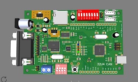
32u4-CAN development board
 The board is loosely based on Arduino* Leonardo* using Microchip* ATmega32U4* microprocessor and MCP2515* or MCP2518* as CAN controller and MCP2551*
CAN transceiver which is wired to male DB9 connector. 2pin screw type
terminals for direct connection to the bus and a Molex 2 pin header provides
expansion connection to prototype board. In addition the board has additional circuitry for micro SD
card which can be used for storing data, logs or other information generated
by user programs and not limited to OBD.
At this time we are only offering bare unassembled PCB's, user is required to have the board assembled with their own components.
The board can be assembled with minimal configuration to emulate Leonardo
(r). It can optionally have SD card and/or CAN components added or used with
expansion for custom circuits or other versions of CAN / K or L line
circuits
Available through Tindie
Features of the 32u4 board
o
Microchip
ATmega23u4 microcontroller based design.
o
Arduino UNO
expansion headers for stacking of other expansion modules
o Mini SD socket
for local logs, no need to computer
o
Option for MCP2515 or MCP2518 CAN controllers
o SD and CAN controllers are selectable via 4 different chip select pins
o Groove (2mm) headers for I2C and UART connections simplifies connections to other devices
o Chip select are via DIP switches or via 0.1" jumpers
o
Power input via 5.5x2.1 barrow connector optional
o
Power input through OBD port
o
On board 5v 1A power regulator and 3.3V 0.500Ma or 1A power regulator
o
Programming via standard ISP header or USB mini-B socket, no programmer required
but will need to have initial boot loader installed
o
CAN v2.0B up to 1Mb/s data rates
o
High Speed SPI interface (10MHz)
o
Standard and extended data and remote frames
o
LED indicators
o
Power
o
Tx, Rx
o On board
LED (D13)
o
Board size 101mm x 66mm (4in x2.6in)
Arduino Bootloader & programming
As the board is loosly based on Arduino Leonardo, header pins are mapped
to those of it or Arduino UNO. Therefore Arduino Leonardo boot
loader can be programmed in through the ISP header to utilize further
programming through the USB connector. The ISP header can be used for
programming if no boot loader is desired. As Sparkfun mini pro also
utilizes same controller, boot loader of the 5V 16Mhz version can also
be used.
Power
Powering the board is accomplished through 4 ways USB connector
limited to USB port limitations normally 500mA, Vin pin (RAW), OBD
connector or DC barrel isolated by steering diodes into 5V regulator.
3.3V voltage is derived from VR2A or VR2B regulators depending on the
need
Switches / Jumpers
SW1 is used for chip selection for SD card and CAN controller
chip, divided into 2 groups 1-4 and 5-8 and wired to digital pins
D11-D8, Group 1 controls CAN controller and group is used for selection
of SD card.
SW2.1 feeds R11 & R12 voltage divider into A5 to monitor voltage
applied into pin 9 on the DB9 connector. the signal can be used to
monitor battery voltage of Vehicle or a project. running of this
connection. (normally open)
SW2.2 control interrupt pin from CAN controller and steers it
into D7 (normally open)
SW2.3 connects AVcc to either 5V rail or external AVcc connector
(normally closed)
SW2.4 is analog Reference switch connecting it to 5V rail
(normally closed)
In place of switches Molex headers can be used.
CAN controller chip
2 foot prints are provided and are over lapped as not to solder both
chips in. An MCP2515 or MCP2518 can be installed as the protocol CAN
chip
Please reference schematic for passive components related to each sub
circuit
CAN Termination Resistor
According to the Can-Bus specification, a 120ohm terminating resistor needs to be
placed across the CANH and CANL lines at each end of the Can-Bus. Termination resistor
is built onto the board and can be activated using jumper link on header labelled
"J1 Term".
OBDII cables
There are numerous different pinouts for the DB9 to OBDII cable.
We had made the DB9 pinout follow most common wiring for OBDII cables currently
being sold. However we
strongly encourage that you check your cable to match the wiring matches the
board.
To make your own cable please follow the below pinout.
| Signal Description | OBDII | DB9 (female) |
| J1850 BUS+ | 2 | 7 |
| Chassis Ground | 4 | 2 |
| Signal Ground | 5 | 1 |
| CAN High J-2284 | 6 | 3 |
| ISO 9141-2 K Line | 7 | 4 |
| J1850 BUS- | 10 | 6 |
| CAN Low J-2284 | 14 | 5 |
| ISO 9141-2 L Line | 15 | 8 |
| Battery Power | 16 | 9 |
32U4 board documents:
-
Schematic
PCB layout files
Gerber Files
ATmega32U4
MCP2515 Datasheet
MCP2518 Datasheet
MCP2551 Datasheet
OBD-II Parameters ID's
Bill of Materials
Assembly / board manual
Arduino MCP2515 CAN-BUS library
DB9 to OBD-II breakout
The break-out board provides terminal connections to individual pins through a DB9(female) connector. As the board does not have any active components as is generic and can be used in other application. Follow the <link> for files
32U4 prototype board:
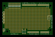
This is a companion to the 32U4 meant for stacking or piggy back expansion board to experiment with additional circuitry. However as it is based on Arduino* UNO pin layout it will fit onto other Arduino boards like Arduino UNO, Leaonardo and the likes.
Available through Tindie

NOTE:
* Copy right and trademarks of their respective owners / manufacturers