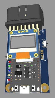
ESP32 CAN gateway shield
 ESP32
is a very powerful processor with a lot of hardware drivers with in the chip
that a lot of users are not taking advantage of and one of them is CAN
module. Adding a small CAN transceiver chip with supporting biasing and
voltage regulator we turn into a small module to which the ESP32 is plugged
and turning it into a flexible CAN gateway.
ESP32
is a very powerful processor with a lot of hardware drivers with in the chip
that a lot of users are not taking advantage of and one of them is CAN
module. Adding a small CAN transceiver chip with supporting biasing and
voltage regulator we turn into a small module to which the ESP32 is plugged
and turning it into a flexible CAN gateway.
Though the board is very basic it does have number of connector for CAN, I2c
and UART(serial) busses which can be used for expansion and can be
configured in various ways dependant of software implementation.
As the ESP has number of communication capabilities, the board can be
simply configured as WiFi or BlueTooth gateway. or a simple CAN to serial (TTL)
adapter. The I2C port can be used to expand the board to other modules
or simply as tranceiver for other projects.
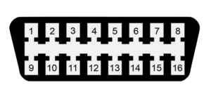 |
OBDII Pin
6 to CAN H |
Features of the 32u4 board
o
Plug in
shield for 30pin ESP32 development kit1 board.
o
Data
Rates: up to 1 Mbps
o
Compatible With ISO 11898-2
o
Cross-wire protection
o
Over temperature (thermal shutdown) protection
o
EMI and ESD CAN bus protection
o
Loop back (LBK) feature available driving GPIO33 high
o
CAN
tranceiver using Rx = D4 and Tx = D5
o
Operating
range of 7 to 15.5 volts (12v system)
o
Can utilize CAN B connector or 4 pin 2.54" header
o
Switch
for putting CAN into Read only mode (disable transmit driver)
o
CAN
termination solder jumper of switch
o
2 serial/UART connectors JST / 2.54
o
2
I2C connectors JST / 2.54 (internal 2.54 meant for 0.91 oLED
ssh1306 display) externally expandable through JST connector
o
LED indicators
o
Power
o
3 General purpose
o
1 R/WR CAN status
o
PTC
fuse and diode polarity protection
o
Voltage
divider to measure pin 16 battery voltage
o
User
button on back of PCB
o
Board size
44mm x 66mm (4in x2.6in)
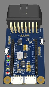
Power
Powering the board is accomplished through 4 ways USB connector
limited to USB port limitations normally 500mA, Vin pin (RAW), OBD
connector or DC barrel isolated by steering diodes into 5V regulator.
3.3V voltage is derived from VR2A or VR2B regulators depending on the
need
Switches / Jumpers
SW1 Used for R/RW (disabling transmit circuit in the
CAN driver
Down puts in into Read only / UP enables transmitter and puts in into
RW mode
SW2 User function switch
SW3 CAN termination Up enables 120
ohm resistor Down disables termination
Board documents:
-
Schematic
PCB layout files
Gerber Files
Bill of Materials
Assembly / board manual
STL case files
NOTE:
* Copy right and trademarks of their respective owners / manufacturers