| |
- This came out as of frustration with my normal
night table light. It was driving me crazy and blinding when I
turned the light in middle of the night. On top of it was trying
to find the power switch. So decided to make a light that I can
easily find switch in the dark and have soft start so that I
would not get blinded by.
Option came down to LED's as light source and the latest
generation of white LED's come in variety of color temperatures
and are incredibly bright, they are very energy efficient,
durable and virtually last forever. However to control their
brightness you need to limit current supplied to them by ways of
resistors or varying their On/Off times. Changing current can be
a bit messier then by simply changing pulse width modulation how
long they are turned On and off. Therefore utilizing a very small
microcontroller we can do number of different things with the
lights and how it reacts to our inputs.
There are number of very small and powerful controllers for
under $1 and with power regulation for the controller and
supporting drive circuitry for the LED and couple of push
buttons, entire control circuit can be assembled for under $3 or
less. Adding your favorite LED to the mix will bring the cost up
to $5-$7 range.
The Microcontroller
The brain of the hole thing is ATtiny84 microcontroller,
which is a 14 pin chip. Could have used ATtiny85 which is only 8
pin chip however the ATtiny84 is about cheaper by $0.30 not that
it would break the budget with this project. Both chips can
operate with internal or external oscillator but as the processor
will sit mostly at idle all of its function in this project,
external crystal to run it will be way of overkill. With couple
pins to control it and a pin to drive the transistor driving
LED the extra pins will not be used either however we need 3
pins to have the chip programmed. Therefore we will reserve
those 3 pins for any programming if we decide to update code for
the light add something to it or modify algorithm of how the
light is being controlled.
We will use 1 pin for driving power transistor, one pin for
switch back light illumination when main light is off and 3 pins
for controlling the light though if needed this can be
accomplished via single analog pin and voltage divider. However
there is no shortage of pins and processor and switches and
power drivers will be enclosed in single box we don't have
to worry about number of wires. So the total comes to 9 pins out
of the available 12 IO pins.
Power Supply
As the processor can operate up to 5V and most likely the LED's
used will require 12V and power supplies / adapters are
generally 5 or 12v. Therefore will need to step down the 12
volts down to 5V. The quickest way is to use linear voltage
regulator as the processor requires very small amount of current
and we can reduce circuit and enclosure as result of it.
Drive circuit
To drive the LED's, a IRL540 FET transistor is used while
switching ground thus being able to control other voltage LED.
Those transistors can drive at 12A surge and can be turned on
directly driving it with a 5v pulse from microcontroller hence
one of the reasons of using 5v regulator. This way the FET
junction is fully driven with out loosing efficiency from the
transistor. Having a very small junction resistance and high
current drive they will not require any heat dissipation.
Code
The Atmel/Microchip ATtiny just like the ATmega chips are very
easily programmable with Arduino IDE. With some simple logic
layout and some time to figure out the basic algorithm and
functions then extra time to debug it as the pin outs did not quite match the ATtiny
library I used for what was in documentation :-/
One major problem with the tiny core and especially used as
standalone is that they don't have direct serial programming.
therefore they need special programmer or another Arduino board
needs to be used to have them programmed. Secondly you can
not put anything into serial monitor to watch for any variable
changes so debugging takes a bit of extra effort.
Never the less the code is available
<here>
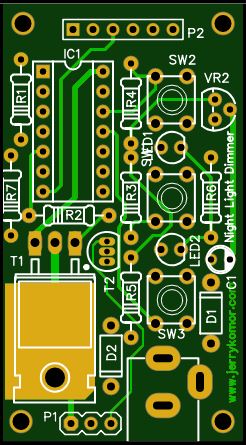
Schematic.
It can not be any simpler then this circuit. We have power input
with couple capacitors for filtering, voltage regulator powering the processor.
What's not on the schematic is a diode on the input to protect
it from reverse polarity to the regulator. 3 switches for
control with pull up resistors and tiny capacitors to provide
some debounce though software provides a bit of filtering as
well. Finally a IRL540 though any N-channel FET can be
used for as long as it can be switched with 5V on gate. The 540
was chosen mainly because it can handle 100v drain to
source, can be switched with processor logic levels and can
drive 28amps at 25'c. So a 100mA LED will not even make it worm
and will not require any heat dissipation. A small LED is used
for back light of switches and brightness is controlled via
software.
Lastly the extra pins
MISO,
MOSI,
CLK and
RESET are left unused for any software updates
Features
|
|
|
|
|