OBD logger
 Off
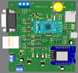
line OBD logger
based on STM32F105RBT6 for fast data aqusition.
Features 4 CAN and 1 LIN buses. 2x 1MB and 2x up to 8Mb buses. Headers
for HB-06 bluetooth and ESP01 or WeMOS D1 modules provide WiFi connections
Your application firmware will allow data logging into SD card
Off
line OBD logger
based on STM32F105RBT6 for fast data aqusition.
Features 4 CAN and 1 LIN buses. 2x 1MB and 2x up to 8Mb buses. Headers
for HB-06 bluetooth and ESP01 or WeMOS D1 modules provide WiFi connections
Your application firmware will allow data logging into SD card
Features of the OBD logger
o
Powerfull
STM3232F105 microcontroller based design.
o Dual
5v 1A and 3.3V 1A voltage regulators
o Power
and Status LED indicators
o Mini SD socket
for local logs, no need to computer
o Battery backup for controller memory and RTC
o HC-05
Bluetooth communication header
o ESP8266-01
and WeMOS D1 Mini header for WiFi communication
o 4
CAN buses
o
2 CAN1/2 drivers by onboard controllers 1MB
o
2 CAN3/4 via MCP2518FD CAN controllers fast CAN up to 8MB
o
MCP2562 tranceivers on CAN3/4
o LIN
bus
o DB9
connector with CAN1 and LIN buses
o RJ45
for can bus only
o 2
pin screw terminal for CAN1
o 3
pin screw terminal for LIN bus
o Power
applied through DB9, screw terminal or USB port
o
CAN v2.0B up to 1Mb/s data rates
o
Small
board size 94mm x 99mm (3.7in x 3.9in)
Termination Resistor
there is provision for
termination for each of the CAN buses where 2 sets of solder joints per bus
provide a way of adding or removing 120ohn resistor from the bus.
OBDII cables
There are numerous different pinouts for the DB9 to OBDII cable.
We had made the DB9 pinout follow most common wiring for OBDII cables currently
being sold. However we
strongly encourage that you check your cable to match the wiring matches the
board.
DB9 connector
The DB connector only has signals for CAN1 and LIN buses and follows
standard wiring scheme
RJ45 connector
As it only has 8 pins, only the 4 CAN buses are wired into it and follow the
RJ45 connector pinout below
To make your own cable please follow the below pinout.
| Signal Description | OBDII | DB9 (female) |
| not used | 2 | 7 |
| Chassis Ground | 4 | 2 |
| Signal Ground | 5 | 1 |
| CAN High J-2284 | 6 | 3 |
| not used | 7 | 4 |
| not used | 10 | 6 |
| CAN Low J-2284 | 14 | 5 |
| ISO 9141-2 L Line | 15 | 8 |
| Battery Power | 16 | 9 |
| Signal Description |
RJ45 pin |
| CAN1 High | 1 |
| CAN1 Low | 2 |
| CAN2 High | 3 |
| CAN2 Low | 6 |
| CAN3 High | 5 |
| CAN3 Low | 4 |
| CAN4 High | 7 |
| CAN4 Low | 8 |
Board documents:
-
Schematic
PCB layout files
Gerber Files
STM32F105RBT6 Datasheet
MCP2515 Datasheet
MCP2518 Datasheet
MCP2551 Datasheet
MCP2562 Datasheet
SN65HVD23x Datasheet
TCAN332D
MCP2004 LIN Datasheet
OBD-II Parameters ID's
Assembly / board manual
Arduino MCP2515 CAN-BUS library
NOTE:
* Copy right and trademarks of their respective owners / manufacturers