USB-TTL adapter with auto reset
| |
-
One of the most over looked circuits and/or adapters are converters
from one medium to another like USB to serial and in this example is USB to
TTL. Hence we have yet another USB to TTL converter.
Yes there are lots of them out in the market utilizing different
chips. What we did with ours was take the CH340 (C or G) chip added couple of
transistors and few passive components and made a dual purpose
adapter. First fold is a basic USB to serial TTL converter with all RS232 pins routed
to the sides. Secondly we routed selective Rx/Tx/DTR pins to 6 pin header for
standard FTDI pin out used in various programmers. Thirdly,
with couple transistors and resistors we made it auto reset programmer for
ESP controllers. This is especially usefull for custom projects using ESP
chips where need for part reduction is of concern thus reducing overall cost
of the project.
The auto reset eliminates the need for reset button and forcing GPIO0 to
ground in order to put the controller into programming mode
A 3.3v regulator provides 750mA of current selectable between it
and 5.0V to the target board if needed. If jumper is not placed target board
will need to be powered by external power source.
Features
o
LCh340c
or CH340G controller
o
LED indicators
o
Power
o Target
o
Standard 6 pin header for programming
o
All
RS232 signals from CH340 chip routed to outer headers
o
2x3
header for ESP programing with auto reset and programing mode
o
mini
USB connector
Schematic
Gerber files
PCB layout files
(easyEDA)
Bill of Materials
|
|
|
|
_12.5.jpg)
FTDI version with 2x3 auto reset header
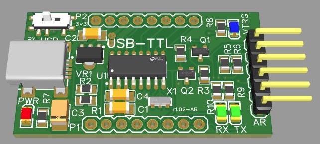
Using same 1x6 header as FTDI but the DTR and CTS
had been replaced with RST
and GPIO0 signals. Note the 2 LEDS, re-arrangement
of resistors and transistors
and no 2x3 header
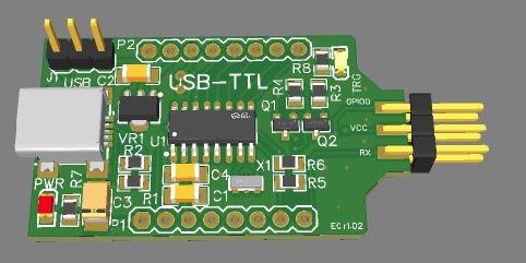
Connector had been replaced with 2x3 header.
|
2023 © All Rights Reserved | PCBhut.com
|