ESP8266-12 4 channel switch with temperature sensors
Purpose of this project came about
cause of couple cheep Chinese webcams that I have in one garage and one looking
at the driveway randomly hanging and not responding. Its very annoying of not
being able to see whats happening when I'm at work and cant get to those cameras
so I figured I'll build a web controlled couple relays and either punch a port
through the router or get to home LAN via VPN and reboot those devices and the
simplest way would be to use NodeMCU chip.
Other part as the device would be mostly just sitting there and waiting for
connections, and as I'm working in garage quite often or like to find
temperature why not add couple temperature sensors and monitor temperature
inside the garage and in front of the house.
For the garage decided to use DHT sensor as it gives temperature and humidity, I
did not cared to much so I used DHT11 which has +/-2' variance, not a great
issue but if I decide I can switch it for DHT22 which has greater accuracy. With
outside temperature I decided to use LM35 sensor as I wanted to use the analog
port on the NodeMCU and have extra pins free maybe for something else later on.
One other thing I did add to this project was light sensor as I had been told I
sometimes I leave the lights on not that I can shut it off but at least it can
tell me that they are on. Simple LDR is used for that which leaves 2 digital
pins free after connecting display over I2C port on 0.9 version of the NodeMCU.
1.0 version has couple extra pins not that they are necessary at the moment.
One thing in the future maybe I'll add routine to track time of how long the
lights are on and watch for movement activity on PIR sensor and send me email
status.
So far main code is done and working.
Next thing to make is PCB with provision for 0.9 and 1.0 chips and maybe a base
Node chip that I can solder onto the board.
Next update to the code I like to add large display clock and have it
automatically sync with NTP server on the internet as it would be nice to have
clock in garage and not worry that it gets reset cause of power failure and WiFi
manager so I would not have to hard code WiFi credentials into the code which is
most annoying. But for now current code is <here>
will all necessary libraries <here>.
You will have to remove the .txt extension form the code file and extract the
library archive and install it into Arduino IDE
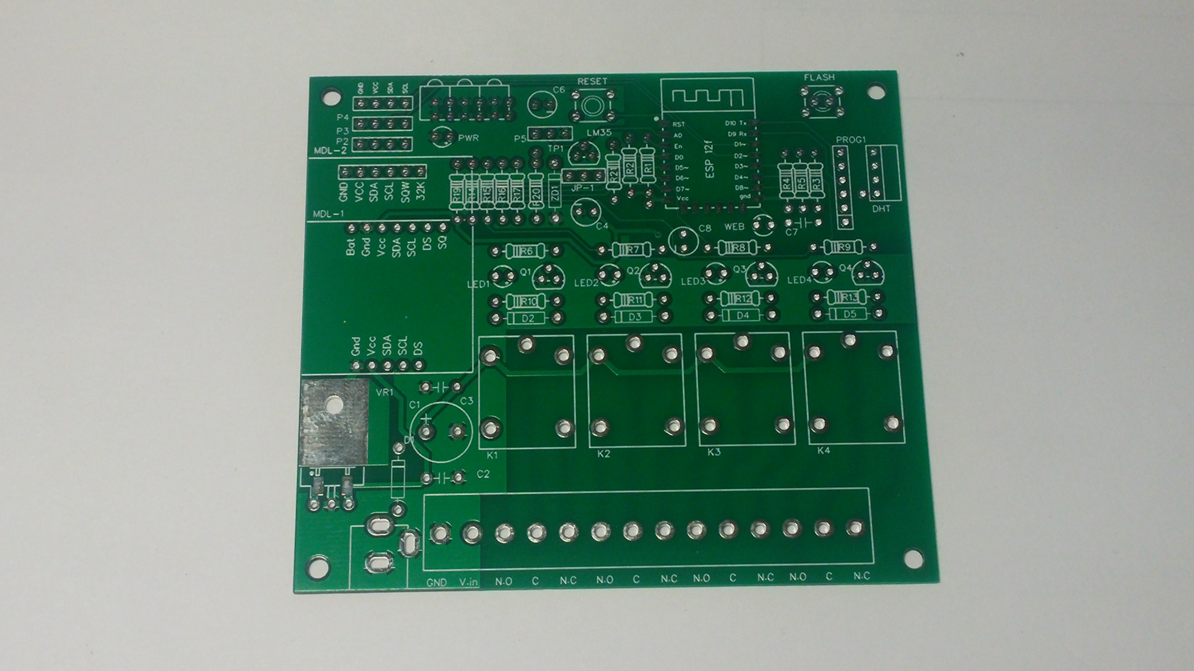
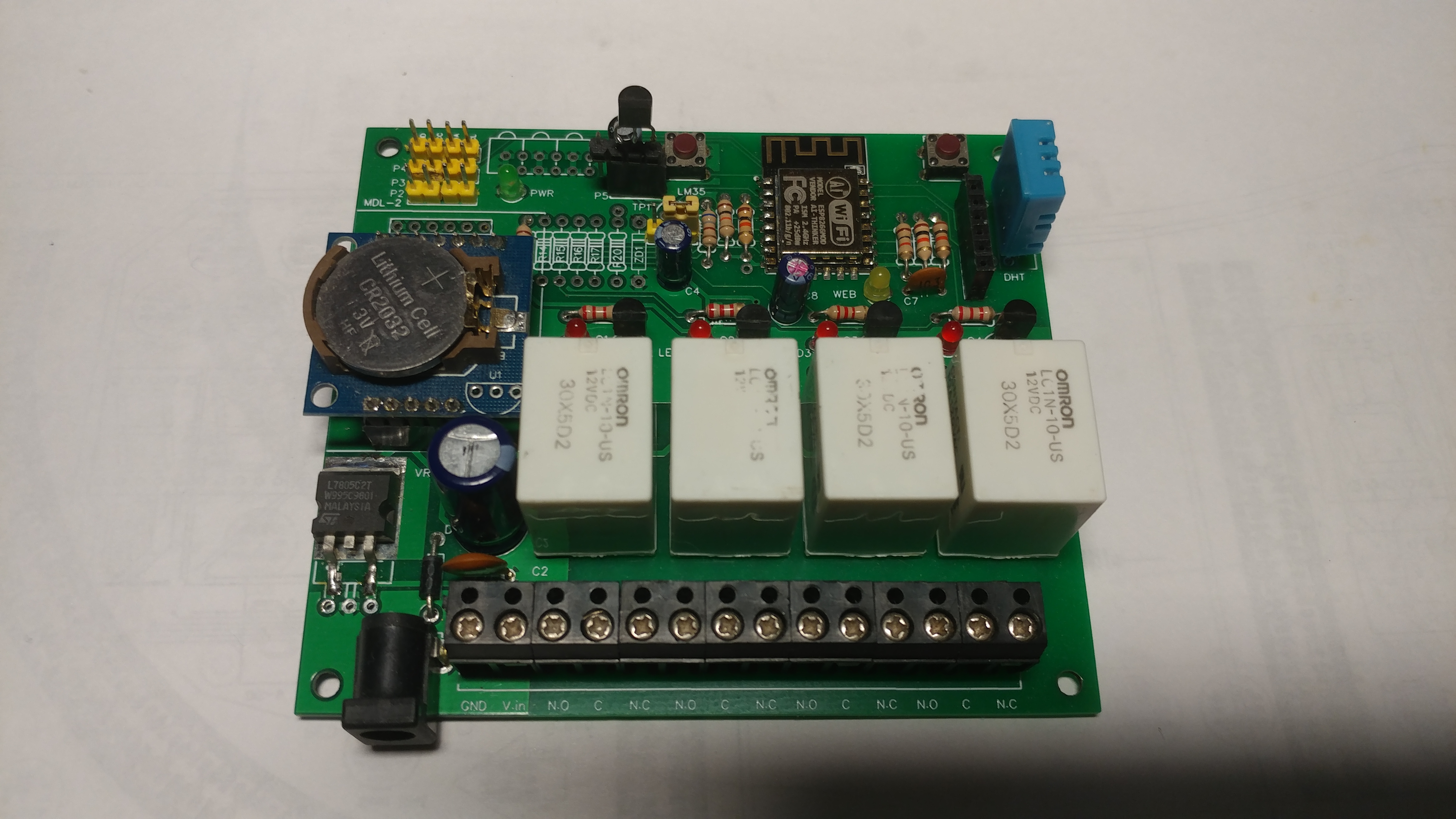
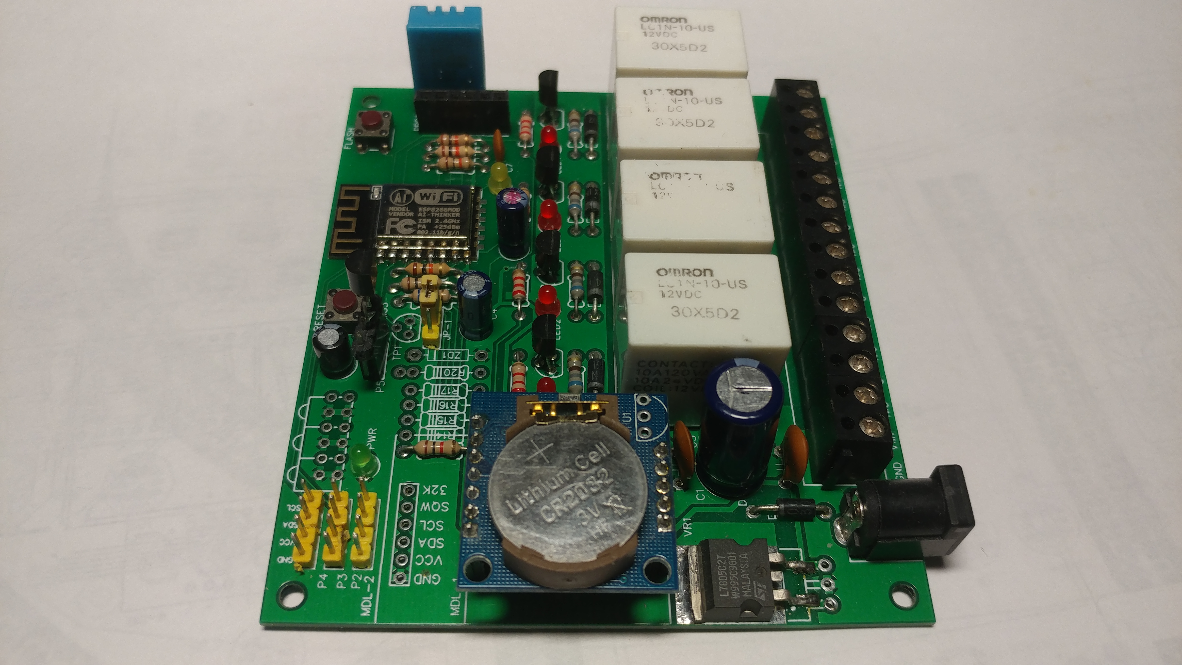
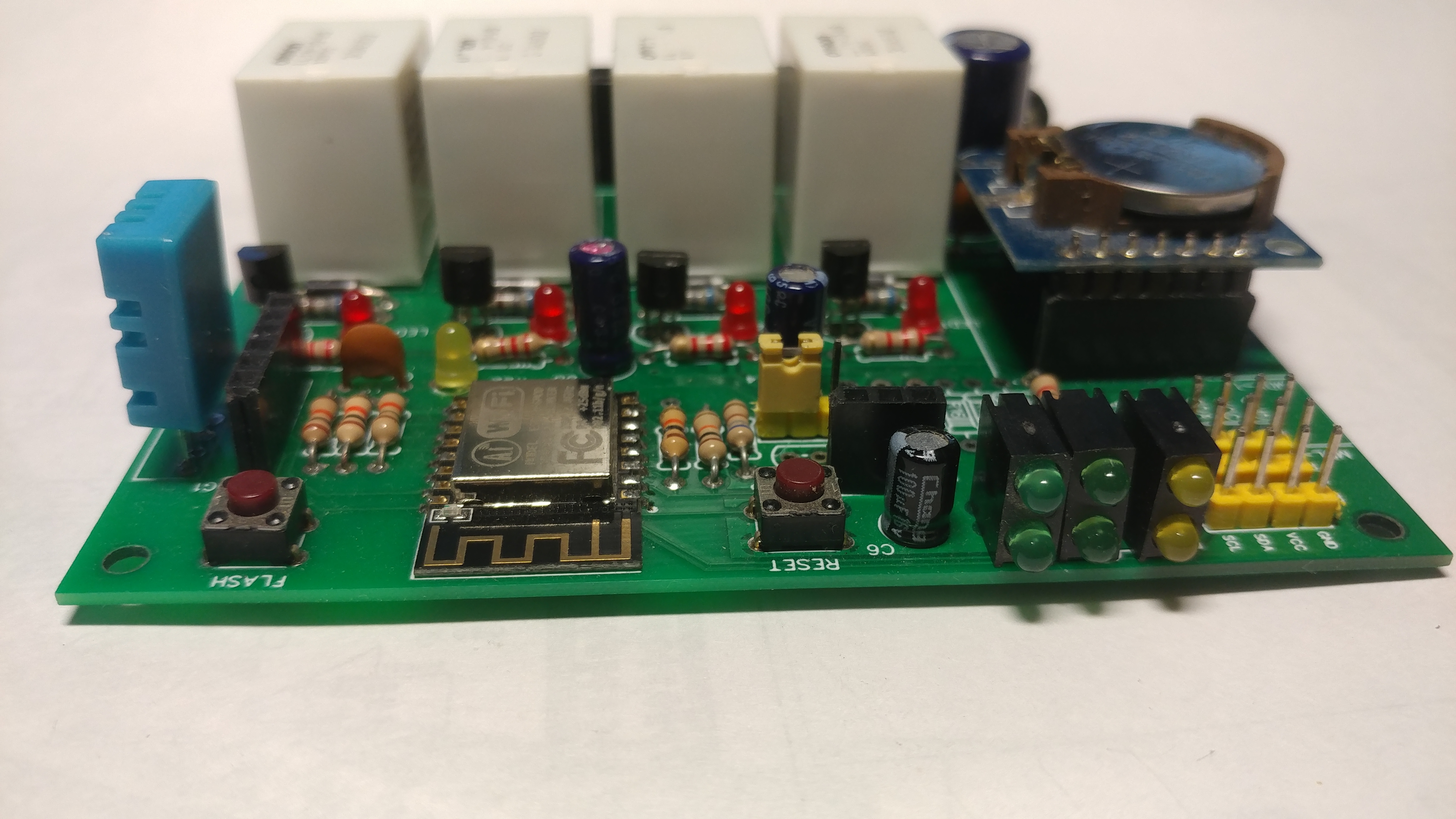
Hardware

Wanted to make the controller as simple as could be and to
minimize on components. With the heart of the controller being ESP12 module
which has all the necessary circuitry with CPU core, memory, WiFi radio and
serial interface for programming. Additional components are hand full of passive
parts and small power conditioning regulators. 4 relays are driven by small
transistors as the ESP can not provide enough current to drive the coils. The
PCB was designed to host DHT and LM35 temperature sensors with provision of
additional digital single bit to drive or monitor other sensor ie LDR for light
sensing.
PCB was laid out with EasyEDA and can be found at
JLCPCB
if you like to order or find more information.
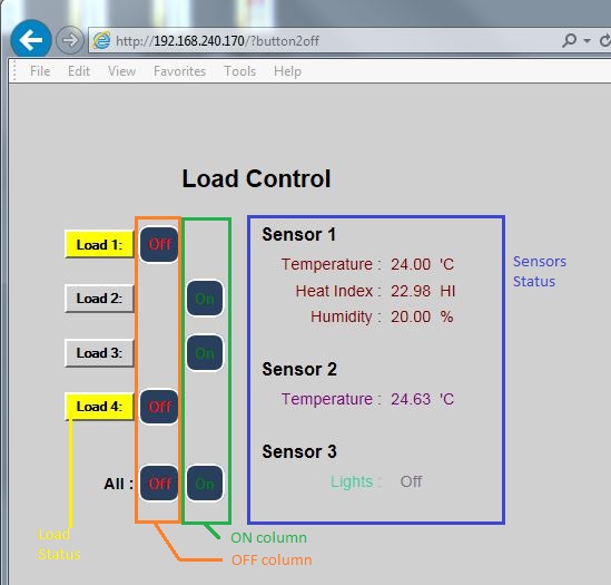
Web interface / Software
Tried to make the web interface as simple and as possible and had divided into
control and sensor status display.
Load status column is dynamic where the load channel button turns yellow when
energized and goes gray when turned off. The controller is setup currently as
true positive meaning that the output pin on controller is positive when
energized. Column On and Off are controlling state of the output. The code is
written in a way that for all both buttons are showing all the time where as for
individual load control channel On and Off buttons are alternatively shown.
Thought was that there is no need to show the On button if the load is On. This
can be changed in each table row output control. The IF statement controls how
the load is shaded and also selects if On or Off buttons are shown. If there is
no need to control shade of the load button cell nor controlling which button is
shown by removing/ commenting the IF directive and un-commenting the 3 lines
below it.
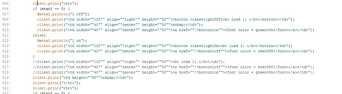
At the moment the display refreshes each time the load control button is clicked
on or refreshed once every 15 seconds automatically. When connecting to the
device, actual state of the output will be shown due to that there are status
flags for each output and are used within the HTML code section.
Like to hear / see other peoples changes and modifications to the code or even
custom code that they had wrote. Please send me
email and let me
know if you lime me to share your code here
Some pictures
PCB layout files EasyEDA
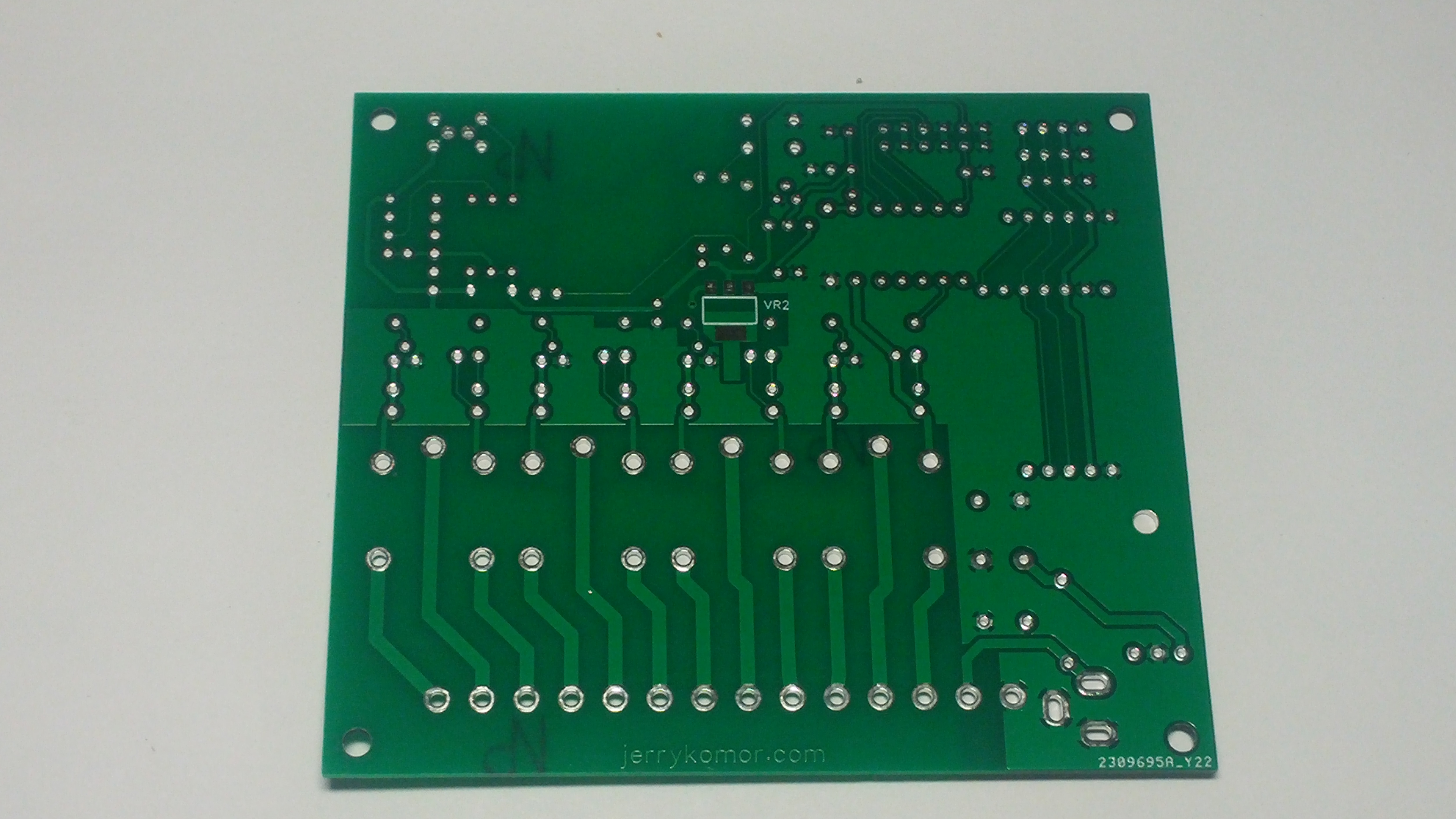
Board top
Board
bottom
Assembled top
Assembled CRT (ds1307)
Assembled front (optional front LEDs)
Source code example v.0.1.1
Source code example v.0.2.1.1.1
adds DST time change and improved HTML handling