• About
  • Contact Us
 
  • Home
  • Products
    • All
    • Blank project PCB
    • Projects & Instructions
    • Proto boards
  • Services
  • Techical notes

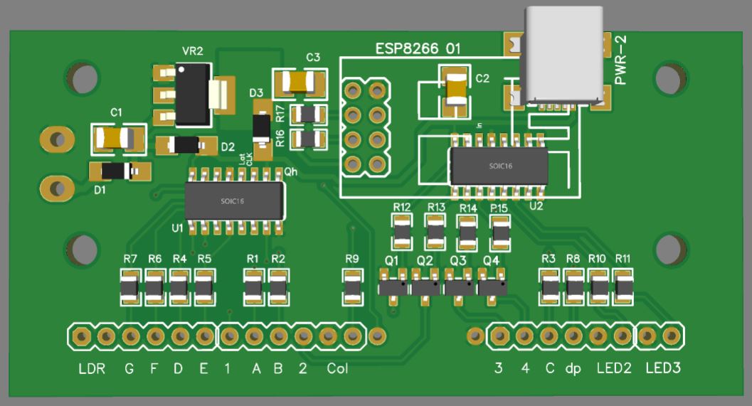
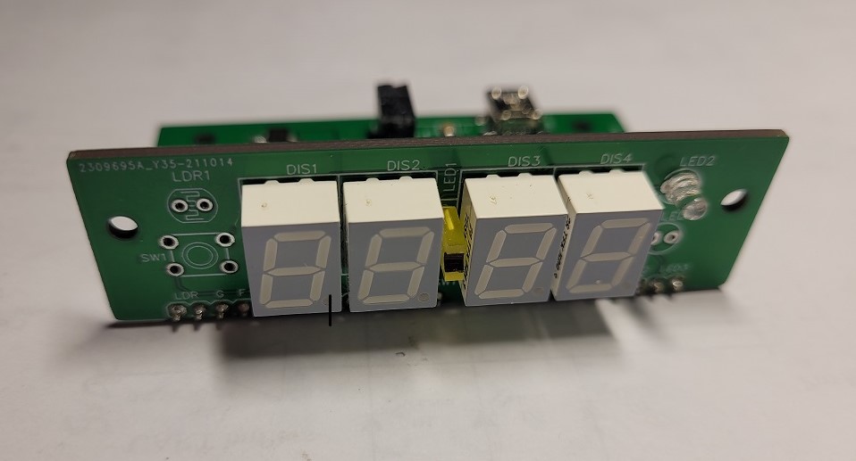
ESP-01 2x 74hc595 clock


  • The clock is based around ESP8266-01 module and 2 - 74hc595 serial to parallel shift registers as the core for the clock. 4 transistors provide sing current and driver for each display and resistors on each segment provide current limiting.

  • Original revision, all power regulation of 3.3v is applied to entire circuit.  Revision 1.02 takes adventage of 2 regulators 5.0v for logic and driving display and 3.3v for the ESP SoC module. The board can be powered through wired connection or USB mini B or ether USB mini B or USB B connector
     

  • A plug in board through 2 inline headers provide connection into display board. A smaller board with 0.36" displays with LEDs for colon and 2 additional user LEDs provide visual display. push button switch can be utilized for user function connected to Rx pin on the ESP unfortunately LDR can not be utilized as 3 signals from the ESP01 are used to drive the 74hc595 and 4th pin is connected to the push button. Initial release of the 0.36 board has only single LED for colon, Revision 1.01 adds additional colon LED and the 2 are separated by resistors.
    0.56" version of the display is only 0.2" taller but still the same width which will fit into the same case but will need different front frame

    Versions of the boards are available on our Tindie


    Features

       USB A  or mini B  or  flying lead power input
       5 and 3.3 volt regulators
       2 74hc595 shift registers
       socket for ESP8266-01
       4 MOSFET driver dransistors


      Documents

         Schematic  (display & controller board)
         Bill of Materials
         PCB laybout on EasyEDA
         3D main case (stl)
         3D face case (stl)
         Sample clock code


optional display for making a clock


2023 © All Rights Reserved | PCBhut.com